


INDUSTRY FOCUS: INNOVATION UND TECHNOLOGY
Extract from the 3-volume handbook “Rolling Stock in the Railway System”
Starting from the fundamental goal for the planet to drastically reduce greenhouse gas (GHG) emissions, the current strong trend in the rail sector is to develop zero CO2 autonomous passenger trains. Realisations of urban equipment on battery circulate, but if the batteries answer zero CO2, they still have some disadvantages: a limited autonomy, a long recharging time, a limited lifetime. The thermal traction trains do not have these disadvantages but they pollute, their days are counted, they will gradually disappear.
The equation to be solved is as follows: zero GHG emission + zero overhead lines + high autonomy + fast recharging = future transportation system.
A promising solution to at least partially solve this equation seems to be developing rapidly at this time: the hydrogen fuel cell.
The fuel cell (FC) could lead in the future to a gradual abandonment of diesel engines and even to the disappearance of catenaries. This technology has been known for a long time, Sir Williams Grove developed his fuel cell prototype in 1839 and the first real applications were for the American space programs (Gemini and Apollo) in the 1960s. Now fuel cells are entering progressively in the world of land transport, automotive and rail.
We can say that a real revolution is happening in the rail with a new way to feed trains. There was originally coal, then electricity and diesel, today a new energy vector enters the scene: hydrogen. The breakthrough is still timid but the obligation to drastically reduce CO2 emissions in the shortest possible time plays in its favour, another candidate is on the ranks, these are batteries, their technology is advancing rapidly but to date hydrogen remains the only alternative to the thermal engine for suburban and intercity trains on non-electrified lines, and there are still many.
There are different fuel cell technologies, depending on the fuel used, the type of electrolyte, the operating temperature. The description below is limited to the Proton Exchange Membrane Fuel Cell (PEMFC), the most widely used fuel cell for railway applications to date.
A fuel cell is only an electrochemical converter as battery but without internal energy storage, the fuel storage, here compressed gaseous hydrogen, is made outside in tanks. The hydrogen chemical energy is directly transformed into electrical energy via a reduction-oxidation reaction (redox reaction): hydrogen oxidation by the oxygen of the air.
The chemical reaction is as follows:
At anode side (negative electrode): H2 → 2H+ + 2e–dissociation of molecular hydrogen in protons and electrons
At cathode side (positive electrode): ½ O2 + 2H+ + 2e– →H2O recombination of protons, electrons with oxygen to form water vapor.
The global reaction is simply: H2 + ½ O2 →H2O + electricity + heat
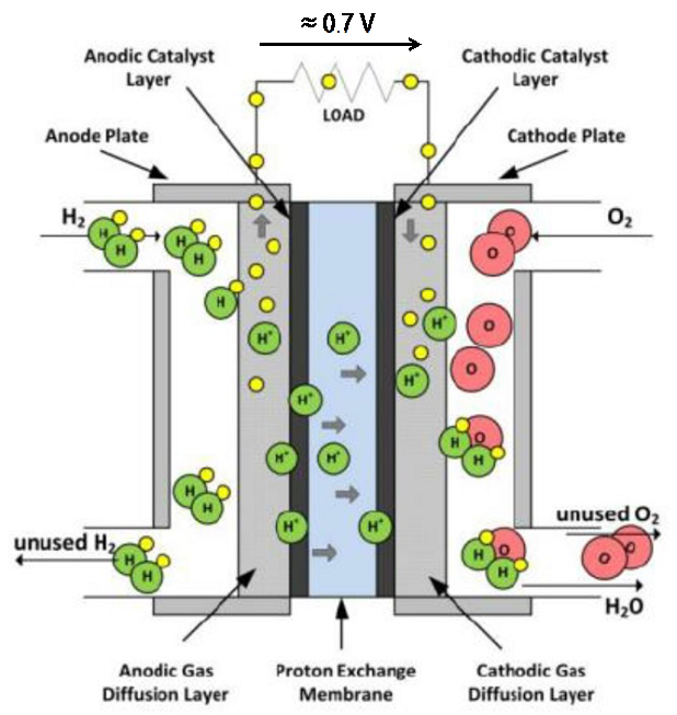
Fig. 1: Principle of an elementary PEM fuel cell
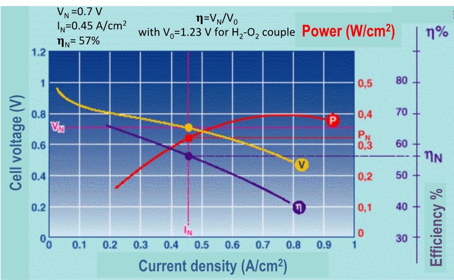
Fig. 2: Main characteristics of a PEMFC: voltage, efficiency, power versus current density
Principle of a PEM fuel cell
Fuel cells produce electricity by “burning” hydrogen, which is three times more efficient in terms of low heating value (LHV) than a hydrocarbon (respectively 33.3 kWh/kg and 12 kWh/kg). Their use has undeniable advantages: zero local pollution (the product of combustion of hydrogen with oxygen in the air is water!), very low noise, zero vibration and a conversion efficiency greater than 50 %.
An elementary cell in composed of two electrodes separated by a solid electrolyte membrane, generally in Nafion® (du Pont de Nemours), the operation temperature range is between 50 °C to 100 °C max.
Molecular hydrogen is introduced at the anode plate in the gas diffusion layer. In the presence of the platinum catalyst layer facilitating and accelerating the reactions, hydrogen H2 is split into positive ions H+ (protons) and electrons. The protons pass through the polymer membrane which has high protonic conductivity but low electronic conductivity leading electrons to follow an external electrical circuit. At cathode plate the protons, electrons recombine with the oxygen of the air to produce water vapor and heat (figure 1)
The theoretical voltage V0 of an elementary cell is 1.23 V, but the mean nominal voltage VN is around 0.7 V depending on the current density (A/cm2) in the cell. The voltage drop is due to the sum of different phenomena: activation of electrochemical reactions at anode and cathode, ohmic resistance of electrodes and electrolyte, limitation of gas diffusion in the layers (figure 2).
The efficiency of the PEM fuel cell is above 50 %, it corresponds to the ratio of the electrical energy produced by the combustion energy of hydrogen.
To deliver a specified output voltage Vstack the elementary cells are connected in series, the stack of cells constitutes the core of the fuel cell, the current Istack delivered is directly linked to the hydrogen flow in the stack:
Vstack = N ∙ Vcel ∙ Istack= 2 ∙ F ∙ FH2/N
with:
Vcell electromotive force of an elementary cell ≈ 0.7 V
N number of cells in series
F 96 845 C/mol (Faraday constant)
FH2 hydrogen flow through the stack (mol/s) with a H2 mole = 2g
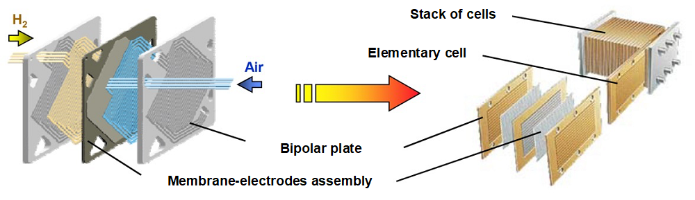
Fig. 3: Elementary cell and stack of cells
The membrane-electrodes assembly (MEA) is the key component, composed of the positive and negative electrodes, the two platinum catalyst layers both sides of the electrolyte membrane in between, its thickness is about 500 μm , the MEA is sandwiched between two bipolar plates which ensure the electronic conductivity, bring and evacuate the products (unused H2, air, water), cool the MEA, the total thickness of an elementary cell is about 5 mm (figure 3).
In fact, to work properly the stack needs several essential auxiliary subassemblies which constitute the balance-of-plant (BOP) to form a complete integral system, in particular (figure 4):
- Hydrogentank with pressure regulator.
- Air compressor with filter.
- Heat exchanger: a water cooling circuit with pump and fan to extract heat from the stack, the stack temperature has to be limited around 80 °C due to the electrolyte membrane.
- Circuit with steam condenser to store and drain the water produced by the stack.
- Device for preheating air and possibly humidifying the membrane.
- Power electronic converter to regulate the voltage at load level when the stack voltage varies
Figures 5 and 6 give some main characteristics of PEM fuel cells used in rail transport.
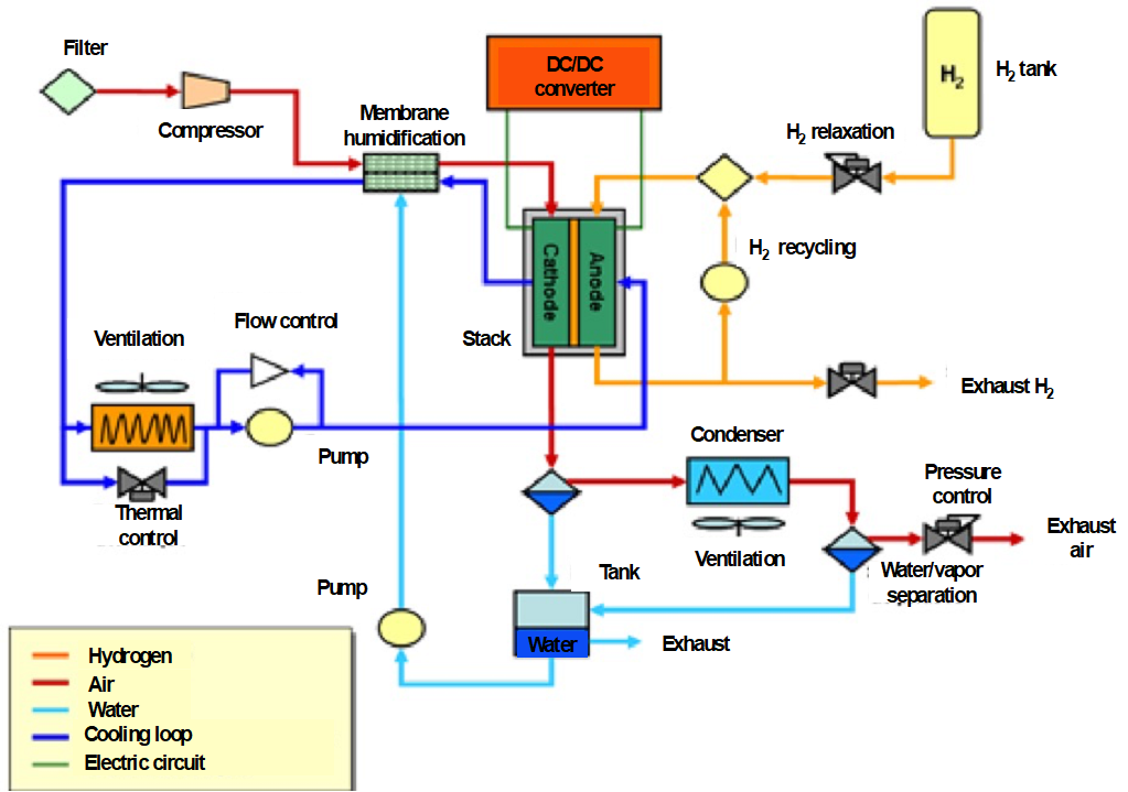
Fig. 4: A complete fuel cell system with accessories (BOP)
Challenges for fuel cells
- Make fuel cells more robust, the present life time of 10 000 h or 20 000 h being too low for rail applications,
- reduce the cost of ownership today much higher than that of diesel engines,
- develop new materials for stacks: bipolar plates, electrodes, membrane, and reduce the quantity of rare and expensive metals as platinum or find a cheaper new catalyst,
- increase the operation temperature for PEM fuel cells.
Hydrogen storage
Hydrogen used in fuel cells is not a primary energy as oil or natural gas but an energy vector like electricity, it must be produced because it does not exist in its natural state.
It has the highest specific energy, 33.3 kWh/kg (LHV) three times better than that of 12 kWh/kg diesel, but it is the lightest gas (90 g/m3 at 1 bar, 0 °C). The consequence is that its energy density at 1 bar, 0 °C is very low: 1000 l of H2 (1 bar, 0 °C) contains 3 kWh, as much as 0.3 l of diesel! Hydrogen has to be compressed or liquefied to reduce the tank volume. Its storage is a real challenge essentially for land transport applications where the space on board is limited.
Currently three main methods exist to store hydrogen:
- Gas compression at 350 or 700 bar
- Liquefaction at -253 °C
- Storage in solids, metallic hydrides
Hydrogen in gaseous form compressed at 350 bar (23 kg/m3) or 700 bar (42 kg/m3), stored in composite structure tanks, is a best compromise between energy density and compression energy cost which represents about 15 % of the storedenergy. The tanks of type 4 are made of a moulded-plastic cylindrical liner providing hydrogen-tightness mechanically reinforced by a carbon fibre, for safety reason tanks must withstand an overpressure test at 2.5 their nominal pressure (figure 6).
The liquefaction of hydrogen at -253 °C increases the energy density at 71 kg/m3 but consumes up to 35 % of the stored energy, moreover the mass and the volume of the tanks are almost identical to those used with hydrogen compressed at 700 bar due to additional thermal insulation to maintain H2 liquid at -253 °C. This last solution is not considered very interesting for rail transports.
The storage in solids, in magnesium hydride MgH2 for example, gives an energy density of 106 kg/m3 and a specific energy of 76 g/kg MgH2, but absorption and desorption kinematics of hydrogen are slow, the process has to be made at 10 bar, 300 °C, to accelerate the reactions. This solution is mainly interesting for stationary applications to store large quantities of hydrogen in refuelling stations for example.
In summary for land transport and for the time being compression to 350 or 700 bar seems the best solution. With the composite tank technologies, it is currently possible to reach 60 g H2/kg of tank mass and 30 g H2/l of tank mass, which corresponds to about 2 kWh/kg of tank mass and 1 kWh/l of tank mass. But research around the world continues with a continuous improvement of the performance of the tanks in terms of compactness, mass and safety aspects.
Hydrogen production
The hydrogen production is another problem. Today 95 % of hydrogen is produced by steam reforming of methane or ethane, which generates greenhouse gas CO2, the “clean” solution is water electrolysis using electricity coming from renewable energies, about 5 kWh of electricity are needed to production one Nm3 (0 °C, 1 bar) of H2 that is 3 kWh, that gives a transformation efficiency of 60 %. Even if this efficiency is not very high, one of the advantages of this solution is that hydrogen becomes a means of storing the intermittent energies produced by solar and wind power plants.
Hydrogen distribution is also a difficult question. Two possible complementary solutions are envisaged: a centralised production with large scale electrolysers with distribution by pipelines or local smaller electrolysers near the utilisation sites knowing that electricity transport is easier than hydrogen transport.
A new way to produce hydrogen and the creation of an infrastructure must be deployed to enable the large-scale development of fuel cells in rail transport.
In summary the methods and means of production, distribution and storage of hydrogen are barriers that still slow down a fast penetration of fuel cells in the rail market. Even more compact on-board storage and the deployment of a network of hydrogen refuelling stations are key points to be addressed.
Hydrogen risk management
The use of energy, in all its forms, gaseous, electric or liquid, presents risks, in particular when concentrated and confined, hydrogen is no exception to the rule. As with any other fuels, hydrogen is likely to cause fire and explosion hazards if the rules of implementation and regulations are not followed, most of the accidents are due to organisational or human factors. The risks of flammability and explosion have been known for a long time in the industrial world, they must be anticipated and mastered at all the levels: design, production, use and maintenance, their probability of occurrence will be kept very low if the rules of prevention, detection, control are applied according the different directives, standards and guidelines in force.
The ISO issued a technical report FD ISO/TR 15916-2014 dealing with basic considerations for the safety of hydrogen systems, and many IEC or EN standards as well as rules and regulations address the subject.
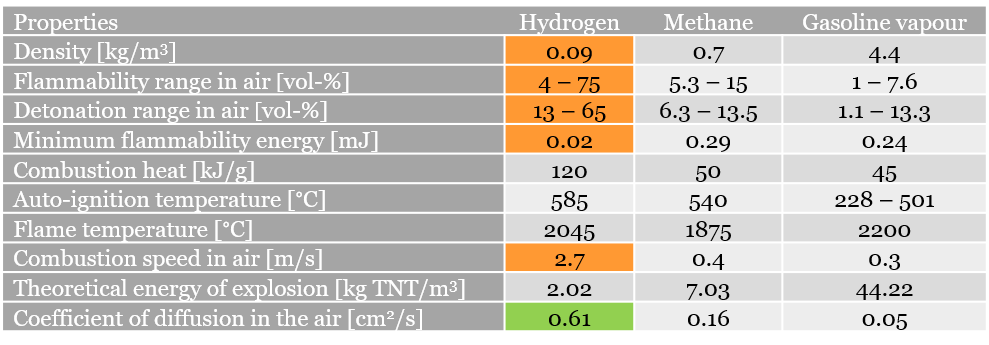
Hydrogen is considered as “highly flammable” due to its physico-chemical characteristics compared with those of methane or gasoline according the chart below (figure 7), the consequences are as follows:
- A tendency to leak easily due to its small density linked to the tiny size of its molecule and its low viscosity.
- A high probability of ignition in the air due to its low ignition energy, a spark or a flame is sufficient.
- But a low probability of explosion in open-air due to its property to disperse quickly.
- A fast speed of combustion leading to a possible deflagration (subsonic explosion).
Considering these hydrogen characteristics several risks are clearly identified and associated procedures of prevention, monitoring, corrective actions have to be taken:
- Against hydrogen leaks: choice of materials, sealing control, H2 detectors, natural or forced ventilation to avoid accumulation above 4 % of H2 concentration in the air, which can provoke ignition.
- Against hydrogen-oxygen mixture inside equipment as electrolysers or compressors: avoid confined spaces, sealed enclosures as hydrogen is light, it has tendency to accumulate in upper parts of equipment, open spaces and ventilation are the best ways to mitigate the risks.
Comparison hydrogen system with other electric supply systems
It is interesting to make a snapshot on the state of the art keeping in mind that all technologies evolve very quickly.
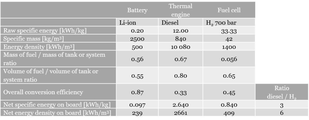
The following table summarises today the three current methods to supply in energy a rail car running on non-electrified lines (figure 8).
- Battery Li-ion.
- Thermal engine fuelled by diesel.
- PEM fuel cell fuelled by hydrogen.
The tank-to-wheel comparison is made for the storage system alone (without the conversion system), it takes into account the different efficiencies to calculate the net energy available on board for traction and auxiliary systems.
Even if the specific energy of hydrogen is three times higher than that of diesel, the ratios are not favourable to hydrogen, the ratio diesel/H2 for the net specific energy is 3, for the energy density the ratio is between 6 and 7.
As an example, for an EMU train requiring about 4 kWh/km to the wheels with an autonomy of 600 km it is necessary to install on board 160 kg H2 700 bar, the complete storage system weighs 2890 kg or 720 l of diesel with a storage system of 910 kg.
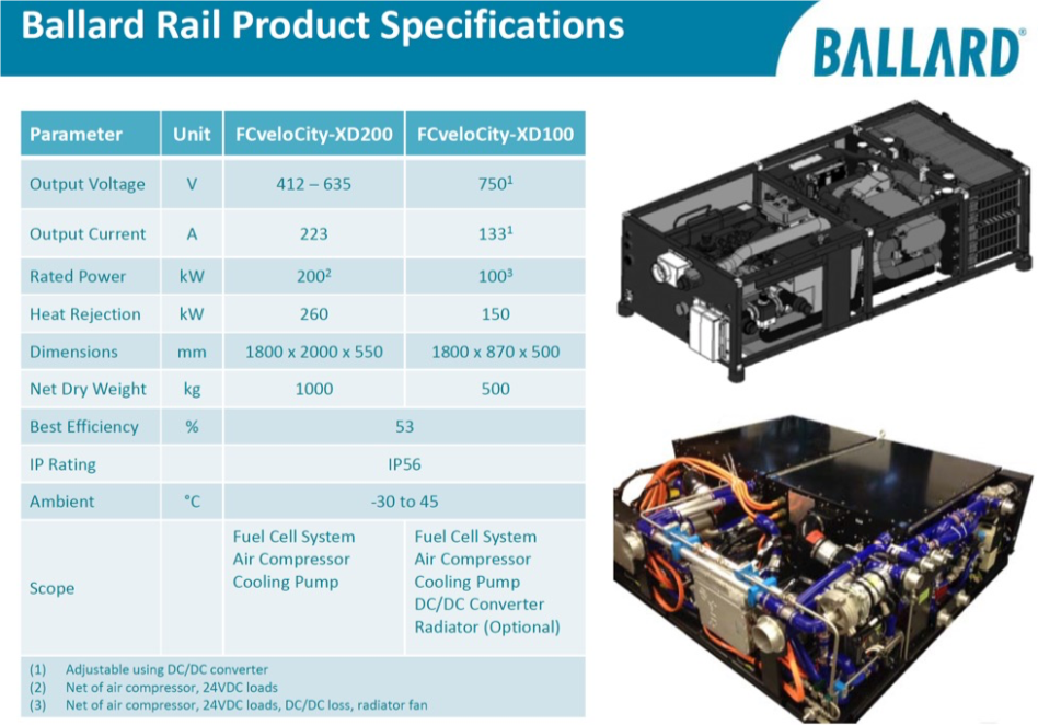
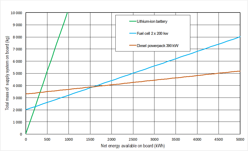
It is also interesting to compare the complete systems, including the energy converters, whose masses depend mainly on the installed power, here about 400 kW, value common to an EMU motorcar drive. The curves of the figure 9 show the evolution of the total mass of the power system as a function of the net energy usable on board. The comparison is made with a 390 kW 3300 kg MTU® 6H1800 R84P electric diesel powerpack and a fuel cell system consisting of two Ballard® FCvelocity® XD200 200 kW, rated at 1000 kg each.
It is also interesting to compare the complete systems, including the energy converters, whose masses depend mainly on the installed power, here about 400 kW, value common to an EMU motorcar drive. The curves of the figure 9 show the evolution of the total mass of the power system as a function of the net energy usable on board. The comparison is made with a 390 kW 3300 kg MTU® 6H1800 R84P electric diesel powerpack and a fuel cell system consisting of two Ballard® FCvelocity® XD200 200 kW, rated at 1000 kg each.
The Li-ion battery system appears as a good solution for low energy needs (100 kWh to 200 kWh) and short distance autonomy (<100 km). For a higher net energy, the fuel cell is interesting up to about 1500 kWh, above 1500 kWh the mass balance is favourable to the thermal engine. Of course, these values will change in the future for fuel cells and batteries with the improvement of respective technologies.
Hydrogen energy efficiency
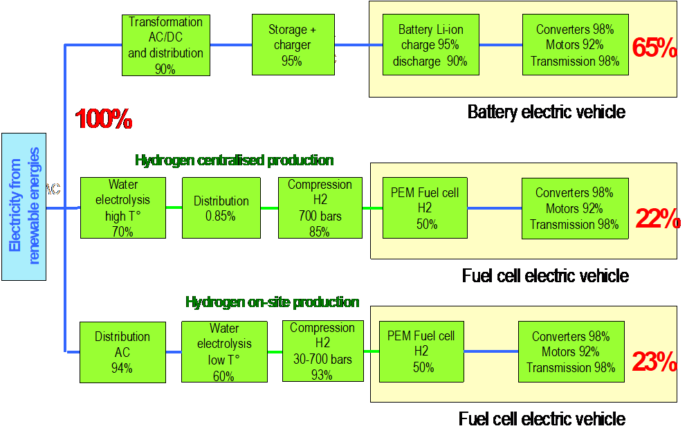
Compared to a battery system, a hydrogen fuel cell system consumes 2 to 3 times more electrical energy (figure 10). This is a fact due to the different transformation yields. But in reality, these two sources of power supply are complementary according to their respective applications, the ideal being to group them as is the case in hybrid rolling stock.
For light-duty vehicles with short-distance autonomy, battery use is certainly the best solution to avoid pollution and electrified overhead lines, but for heavier rolling stock requiring larger amounts of energy over medium and long distances, fuel cells are the unique alternative to the current thermal system for CO2-free transport. Another point to consider is the availability of the train fleet, the hydrogen refuelling time is short, about 10 to 15 minutes, compared to the battery recharging that lasts several hours, this reduces the time of immobilisation in workshop or at the end of line.
In fact, the hybrid trains combining battery and fuel cell are the best compromise solution, the power variations are minimised for the fuel cell which then delivers the average power, while the battery provides the complement, including the peaks of power during starting, the battery recuperates the kinetic energy of the train under dynamic braking, and the fuel cell recharges it in coasting or at very low traction power.
Fuel cell-powered electric vehicle realisations
Numerous prototypes or demonstrators have been developed and tested on line for over ten years in the rail sector, more recently series of trams and passenger trains are in commercial service, hereafter only some of them:
- 2006 Japan: RTRI project with a prototype rail car, FC 120 kW, H2 350 bar.
- 2009 USA: Green Goat BNSF/LLC shunting locomotive prototype FC 250 kW, H2 350 bar.
- 2015 China: Sifang FC tram, world first, FC 200 kW, 7+8 trams in commercial service.
- 2017 China: Tangshan hybrid tram, world first, FC 200 kW + batteries + supercap, commercial service.
- 2017 Germany: World first, Alstom hybrid EMU iLint, first series of 14 trains, 2 FC 200 kW + 2 batteries 225 kW, H2 350 bar.
Furthermore, in addition to 27 series iLint trains from Alstom for the Rhine-Main transport association (RMV), several hydrogen train pilot projects have been launched since 2019 in Germany, Great Britain, Spain, France, Italy and the USA by various manufacturers and project partners, including Siemens, the University of Birmingham, Ballard, CAF/ Toyota Motor Europe as well as Alstom and Stadler, among others. We will soon report in detail on these projects and vehicle developments here.
The Alstom iLint hybrid train is the first passenger train in the world to be equipped with hydrogen fuel cells. A series of 14 two-car trains + 33 options was ordered in 2017 by Niedersachsen-LNVG (Germany) and two of them are in commercial service since September 2018 on the line Buxtehude – Bremervörde – Bremerhaven – Cuxhaven (Lower Saxony).
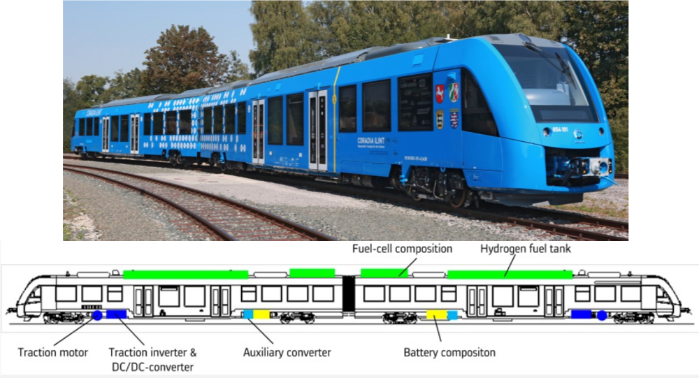
The trainset is composed of two motorised cars (figure 11). Each car is equipped with the following sub-assemblies:
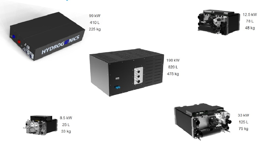
- roof-mounted 200 kW PEM fuel cell composition built from 6 x 33 kW FC HyPM™-HD30 power modules by Hydrogenics (figures 12 and 13),
- roof-mounted X-STORE® hydrogen tanks containing 90 kg H2 at 350 bar by Hexagon-Xperion. (figure 14),
- underframe-mounted Li-ion battery by Akasol: 111 kWh-800 V – 225 kW mean, 450 kW peak (figure 15),
- underframe-mounted traction motor, traction equipment and auxiliary converter.
The train performance is similar to that of Diesel-powered iLint 54, the originate train modified in fuel cell-powered train. With 180 kg of hydrogenthe estimated autonomy is between 600 to 800 km depending on the route profile, operating conditions, stops …, the maximum hydrogen consumption is around 0.3 kg H2/km, the maximum speed is 140 km/h.
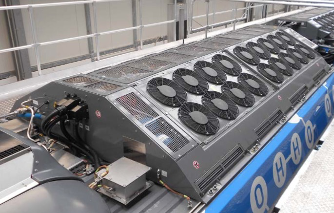
Fig. 12: General view of the 200-kW roof-mounted fuel cell assembly on Coradia iLint (Alstom) 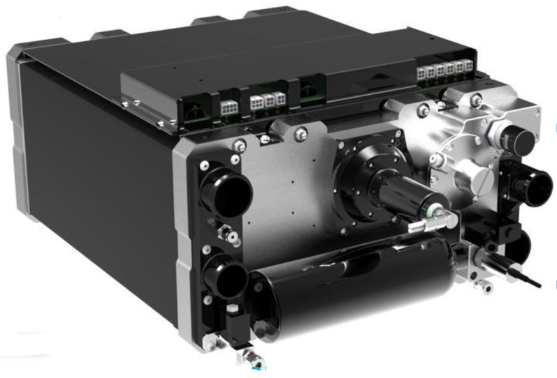
Fig. 13: HyPM-HD30 power module 33 kW used to form the 200-kW fuel cell assembly (Hydrogenics) 
Fig. 14: General view of hydrogen storage 90 kg H2 -350 bar roof-mounted in Coradia iLint (Alstom) 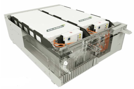
Fig. 15: Li-ion battery assembly 111 kWh – 800 V- 225 kW (Akasol)
Market outlook
In addition to the projects mentioned above, there are numerous projects in Europe and worldwide that envisage the use of hydrogen in rail transport. In addition to fuel cell trains for regional and local transport, there are now also initial studies and projects for locomotives for use in heavy freight transport.
Following the first SPNV tenders for fuel cell trains in Germany, further projects are in preparation, where in some places fuel cell technology will have to compete with battery-powered electric multiple units that can use the existing overhead line.
The extent to which fuel cell propulsion will become established in rail transport also depends, among other things, on local and global energy and hydrogen policies and the resulting production volumes for hydrogen.
Conclusion on hydrogen fuel cells
A clean zero-CO2 rail system must use electricity from renewable sources, the best system is of course the all-electric vehicle supplied by overhead lines that account for 60 % of the networks in Europe. For the 40 % non-electrified lines the supply by a hydrogen fuel cell system is the ideal alternative to the current thermal engine over long and medium distances. If this new mode of supply is still expensive due to its slow penetration of the rail market for the moment it is necessary to take into account in counterpart the cost of installation of catenaries and substations and their maintenance all along their lifetime, without forgetting the problems related to the relative fragility of overhead lines and current collection in degraded climatic conditions.
08.06.2021