This article is an extract from the just published, most extensive compendium on all aspects of rolling stock technology, an international, English-language, 3-volume compendium “Rolling Stock in the Railway System”. Published by PMC Media and edited by the long-standing rolling stock experts Eric Fontanel and Reinhard Christeller, and under the technical supervision of former SNCF and Alstom technical director François Lacôte, more than 30 international authors have created this unique compendium. Three volumes of concentrated knowledge on a total of around 1520 pages and supported by UIC, UITP, UNIFE and ERA. Available as a printed 3-volume set or as individual e-books. More information and a first insight into the compendium and the contents of the three volumes can be found here.
1. Objectives
While there was formerly a great technical difference, or even an opposition or rivalry between trams and urban buses, over the past twenty years the two modes of urban transport have converged and are now rather complementing each other. This convergence becomes visible in many ways. The introduction of low floor solutions makes them both much more easily accessible. While for more than half a century most buses have been powered by fossil fuels and the use of electric buses has been abandoned in many places, it is now the opposite with a strong revival of electric battery- or overhead-line-powered buses or hybrid solutions.
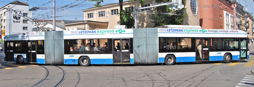
For a long time, trams had the advantage of a much higher capacity than buses, but we see the emergence of double- or even triple-articulated 25 or 32 m long buses, with capacity levels close to that of trams (figure 1). Trams on tyres appear and some buses are equipped with driver assistance systems that ensure that they dock at stations them as closely to the platforms as trams.
We will therefore consider the power supply and traction systems of these two urban transport modes as a whole, trying to identify on a case-by-case basis which technology best meets the objectives of improving individual mobility. and the quality of urban life under the points of view of:
- air quality,
- noise,
- aesthetics
- clean energies and energy savings,
- and practical aspects like,
- the geographical situation and layout of the city,
- economic considerations,
- operational issues.
2 Technologies
Traction systems for trams and buses can be powered in several ways:
- Overhead contact line: Trams generally use this power source with a 750 or 600 V DC power supply wire at 4 to 6 m above the rail level. The electric current returns through the rails and all metallic parts of the vehicles must be earthed, to ensure safety against accidental electrocution.
- Overhead contact line: Trams generally use this power source with a 750 or 600 V DC power supply wire at 4 to 6 m above the rail level. The electric current returns through the rails and all metallic parts of the vehicles must be earthed, to ensure safety against accidental electrocution.
- On-board production of traction energy: This solution applies to conventional diesel buses and the upcoming technology of fuel cell powered trams or buses. In the case of diesel buses, the power chain normally has a mechanical transmission and a high noise level is felt in the area near the diesel engine, which is usually located in the rear of the bus.
- Energy stored in the vehicle: Several objectives and basic principles to meet them are possible:
- Storage to achieve a given drive programme. To ensure a normal one-day programme covering a distance of 200 to 220 km for a 12 m long standard bus, a vehicle energy storage capacity of nearly 400 kWh and a recharge time – usually overnight – of 6 h will be required. A mass of 2 to 3 t must be estimated for the energy storage system using ultra-light So-Ni batteries combined with supercapacitors . Intermediate recharges can help reduce the required storage capacity.
- Battery exchange operation: To eliminate the downtime for recharging batteries, their rapid exchange is an alternative. A system of battery exchange by robots has been developed in China.
- Operation on a line with an overhead line but of which one or several sections are unpowered:
- The storage equipment may be reloaded during the operation on the rest of the line, or
- frequent recharge operations are carried out at stations or at the end of the line. This can be done through a physical or inductive contact to the power supply at some stations. A 30 m long tram may need two Li-ion batteries of about 50 kWh with a mass of about 800 kg each.
- Recuperation: The braking energy is generally recuperated and stored on board in all above-mentioned solutions.
3 Continuous power supply from the ground without overhead contact line
Several reasons may lead to the decision not to provide an overhead contact line or catenary:
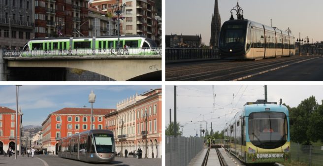
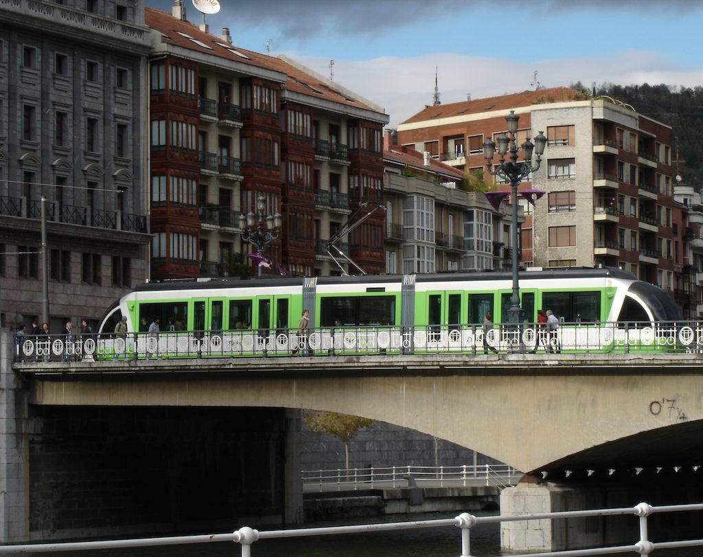
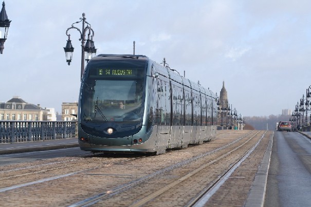
- The aesthetics of the urban landscape with a minimum of visual obstructions in front of emblematic buildings (figure 2).
- Urban conditions that do not easily allow the installation of overhead line masts in narrow streets of city centres, or the difficult anchoring of catenaries in façades too low or insufficiently solid along tram or trolleybus routes.
- Low underpasses that do not allow the use of a pantograph.
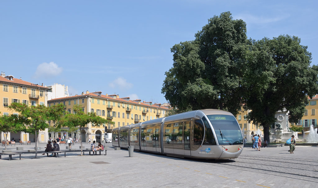
- The need to free up space to allow the passage of very high vehicles (e.g. carnival floats, as in Nice, figure 4).
- The need for a quick access by firefighters, so that there is no need to disconnect the catenary before an intervention.
- The rapid recovery of operations after typhoons.
3.1 Road surface contact rail power supply
A feed through a central contact rail between the running rails for trams in urban space is the first response to the constraints set out above. Unlike the overhead contact line, which is continuously powered by 750 or 600 V DC, it must be ensured that this third rail is arranged so as not to create a risk of contact and therefore electrocution for pedestrians. For this reason, the different versions of contact rails of the old systems of the late 19th century in Budapest, Paris, New York and elsewhere were buried deep in the ground and thus there was almost no risk. Modern systems have been developed in the early 21st century. They have a feed rail divided into segments that are shorter than the vehicles. To ensure that no pedestrian comes in contact with high voltage, each of these segments only comes live when a tram drives over it and completely covers it. One or more contact shoes serve to collect the current. The contact rail and the contact shoes are exposed to soiling and stresses by road vehicles on sections where trams run in mixed traffic. In most cases, these expensive systems are only used on sensitive line sections, while on the remaining sections of the line the collection is done by pantograph.
3.1.1 APS
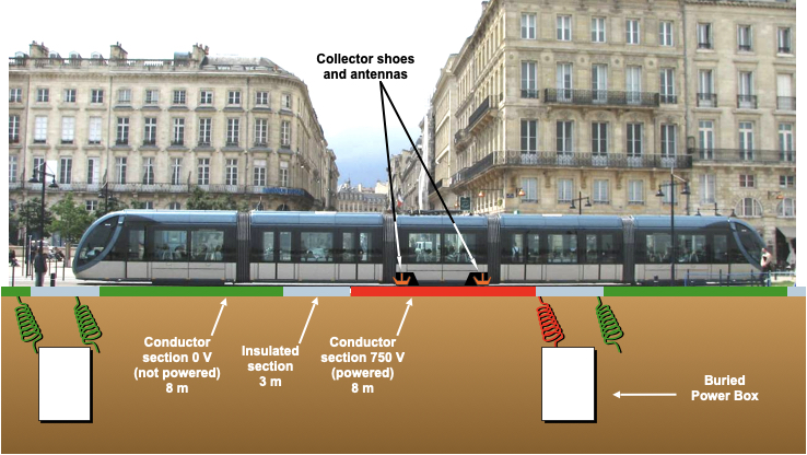
The Alstom street-level feeding system (APS, figure 5) is carried out by a central contact rail (figure 7) consisting of 8 m long conductive segments that can be energised, separated by 3 m long insulated sections (figure 6). The “conductive segments” are powered through switchboxes that contain two contactors each to individually feed two segments. They are buried between the rails every 22 m. The feeding segments are only powered when a tram is fully covering a segment and transmits a coded radio signal to the ground. The electrical energy transmitted by the contact rail is captured by two contact shoes that are similar to those used on metros. They are located in the middle zone of the tram (figure 8). These contact shoes are more than 3 m apart to ensure the continuity of capture during the passage over the isolated area. An on-board auxiliary battery allows for short-distance operation in the event the failure of a segment and when the tram drives over turnouts or crossings. To limit the complexity of the system there is no possibility to recuperate braking energy to be fed back to the line.
This system was first installed in Bordeaux for reasons of urban aesthetics and has been operating since 2003. It is now used in several other French cities and elsewhere in the world, such as Dubai and Istanbul.
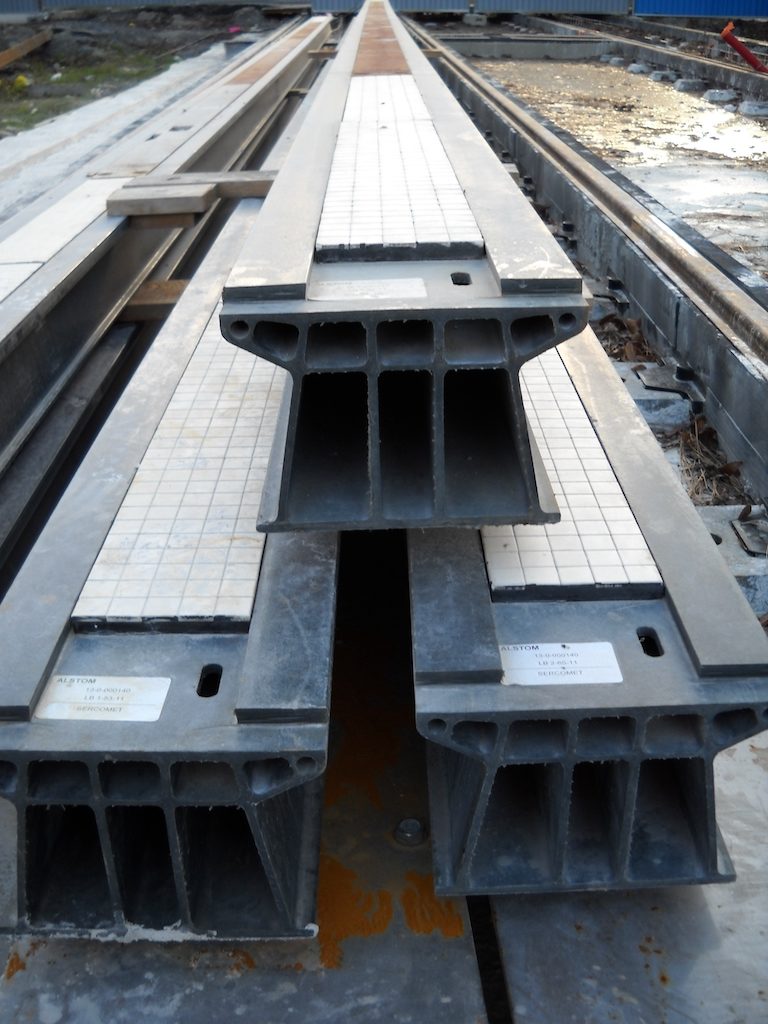
Fig. 4: APS contact rails ready to be installed on the Reims tram line, with their conduits for the wiring between the switchboxes I © Alstom 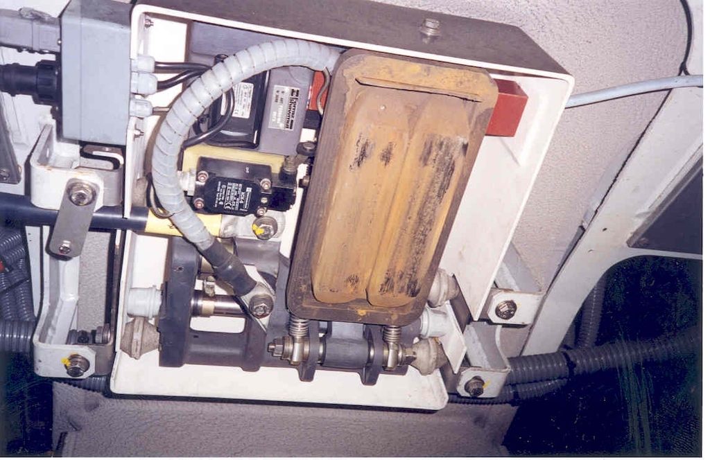
Fig. 5: One of the two APS contact shoes located in the middle of the tram surrounded by the transmission loop of the wireless signal. (Alstom) I © Alstom
3.1.2 TramWave
The “TramWave” (formerly “Stream”) system from Hitachi Rail STS (previously Ansaldo Signalling and Transportation Systems or Ansaldo STS) is also an electromechanical device. A buried feed channel contains 50 cm long vertically movable iron elements that rest on two contact rails, one of which is grounded and the other is connected to the surface where the contact shoe under the tram will pass. As long as there is no tram over it, this ensures a grounding and thus protects pedestrians. The contact shoe in the running gear of the tram is combined with a permanent magnet (figure 9). When the vehicle does not require to be powered by the contact rail, that means in all situations where it is coasting, powered through its pantograph or through an on-board storage or power generation equipment, this contact shoe with its magnet is raised.
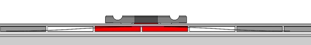
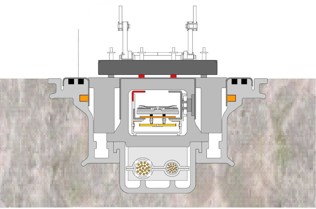
Fig. 10: TramWave in non-activated position. The orange contact provides earthing I © Ansaldo STS 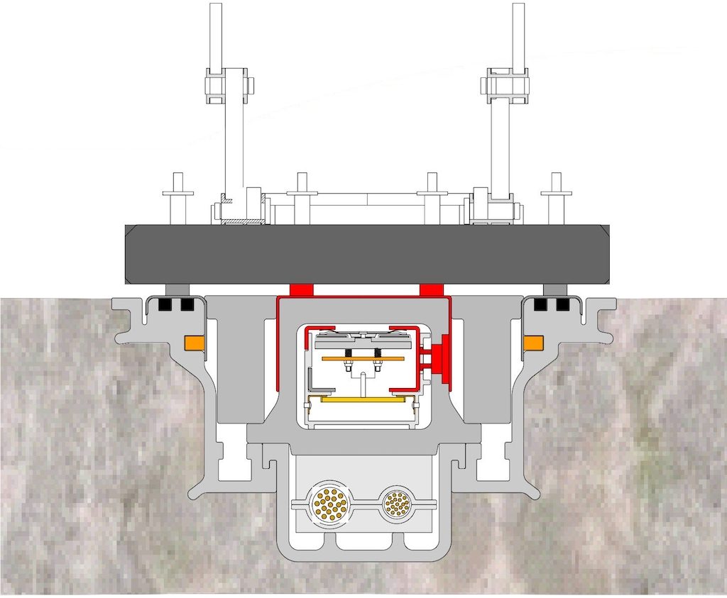
Fig. 11: TramWave in connected position. The raised grey contact puts the red power supply (left) in contact with the surface contact rail I © Ansaldo STS
As long as it is raised, it does not exert magnetic attraction and therefore does not raise the iron elements of the underground power supply (figure 10). When lowered to the track level, the permanent magnet attracts the iron segments and lifts them to the upper side of the feed channel thus connecting the undersides of two electrical rails inside the channel (figure 11). One of these rails is live and the other is connected to the contact surface, thereby energising the rail section under the vehicle. The feeding segments have a length of between 3 and 5 m. The system allows recovery of braking energy in the network.
TramWave has been tested in Italy on trams as well as on urban buses. It equips tram lines in the Chinese city of Zhuhai that suffers from several annual typhoons.
4 Feeding by frequent recharges in the station
In order to minimise the mass and the volume of the energy storage devices on electric vehicles that are exclusively powered by energy that is stored on board, frequent recharges are used when the vehicle is at standstill. On average, a tram or city bus stops every 90 to 120 s for about 20 s, so advantage can be taken of this downtime and a physical or inductive contact can be established to the external power supply.
4.1 Physical Contact
This system consists of a pantograph or another contact element – generally mounted on the roof of a bus or tram – that is connected to a feeding point during station stops. Such feeding points may be arranged above the vehicle or at street or rail level. Several electric bus and tram applications in Germany, China and the Republic of Korea are known.
4.2 Magnetic induction
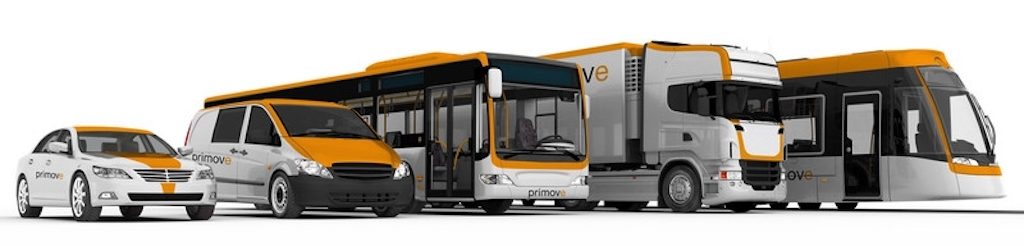
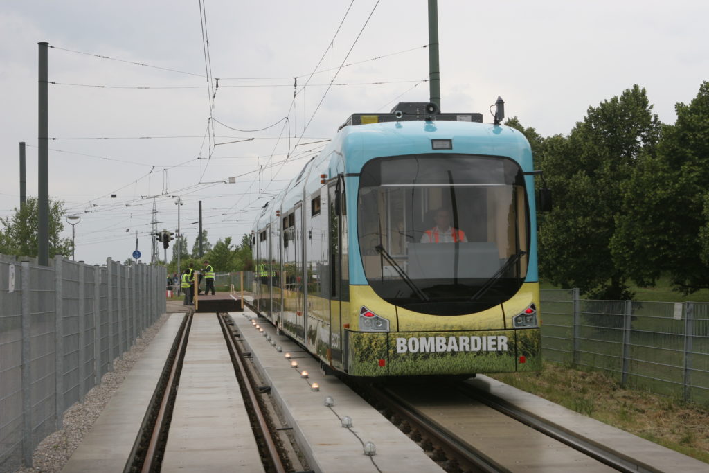
Bombardier’s Primove underground feed system (figure 12) uses the induction transmission technology that is already known in the areas of information transmission, low-power equipment charging, and cooktops. To meet the power requirements of public transport, power supplies between 100 and 1000 kW are available. Thanks to the absence of a physical contact, this system is not subject to wear and therefore requires little maintenance. It is virtually invisible and scarcely influenced by weather conditions. The principle avoids the risk of electrocution and therefore requires no protective measures. However, the power supply is only activated when a vehicle is present. It is in principle possible to equip a line with a continuous supply by induction, but in most cases, it is considered appropriate to use it at fixed points, in association with batteries. Powerful and fast recharging of Li-ion traction batteries during station stops allows to size the batteries to a minimum.
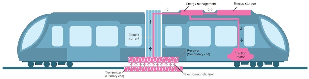
Tests on 600 m of tram line have been carried out in Augsburg. The system is also suitable for use with electric buses, which may use a common infrastructure with trams, but also with trucks and cars (figure 13). The first commercial projects can be found on bus routes in Braunschweig, Bruges, Berlin, Mannheim and Södertälje, all for recharging at stops. These implementations demonstrate the ongoing convergence of different urban public transport modes.
Editorial note: the Primove systems in Berlin and Mannheim have been put out of service.